Controlling Multiple Ancillary Load with Node-RED
The Victron Cerbo GX has Relays built in that allow users to turn loads on/off dependant upon various system parameters such as battery SOC or system temperatures. Many other Victron products also have built in relays that allow for switching of loads, however what if you need to switch a large number of loads or you need to switch loads dependant on parameters that are not monitored by the Cerbo?
Switching of multiple dump loads using node red
In this example we have an 8-way ethernet relay that is controlled using Node-RED running on the Cerbo GX.
- The ethernet relay is connected to our home network and using the software provided with the relay, we assign an available static IP address to the relay.
- The commands to switch the relays are detailed in the instructions that came with the relay, in this case ‘on1’ switches on the first output ‘on2’ the second and so on. To switch the relays back off the command is simply ‘off1’, ‘off2’ and so on.
- Once the GX device is running Venus OS large, the node red screen is available on your home network by entering the IP address of the GX device in your browser followed by :1881 for example 192.XXX.X.XXX:1881 you can also type venus.local:1881 if you don’t know the IP address of your GX device.
- Once on the node red screen, find the Victron nodes usually located down near the bottom of the list of nodes on the left side of the screen.
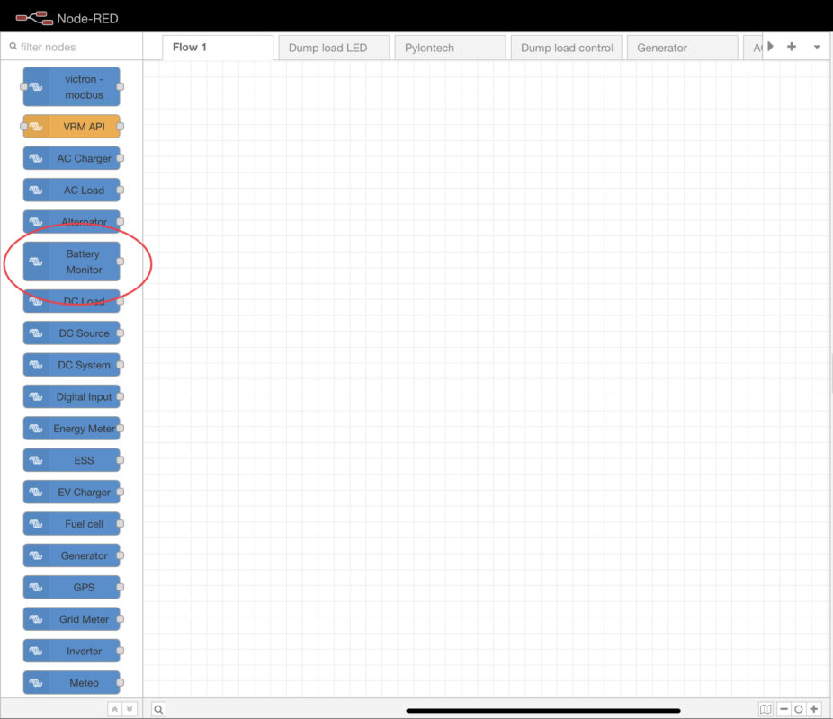
- Drag the battery monitor node onto the screen (once you have a battery system set up on your GX device it should appear as an option in the battery monitor node)
- Double click on the node to enter the node to adjust the settings.
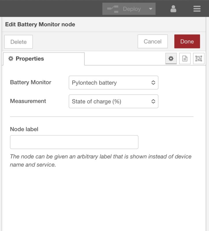
- Select the battery monitor you wish to use (in our case we selected Pylontech)
- Select the parameter you wish to monitor (in our case we selected battery SOC)
- The node will read the battery SOC as a number e.g., 50 for 50%
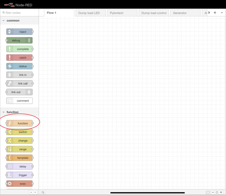
- Next, we need to make a decision based on the value of this number and for this we have used a function node.
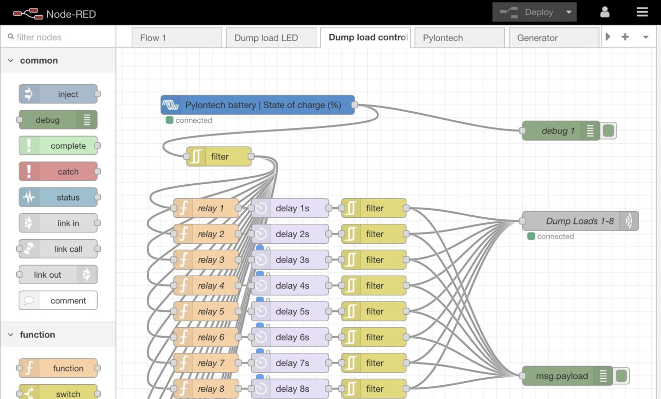
- We have written some logic into the node that gives an output of ‘on1’ or ‘off1’ dependant on the value of the input it receives from the battery monitor (If the battery level is equal to or above 85% send an output of ‘on1’ or else send an output of ‘off1’).
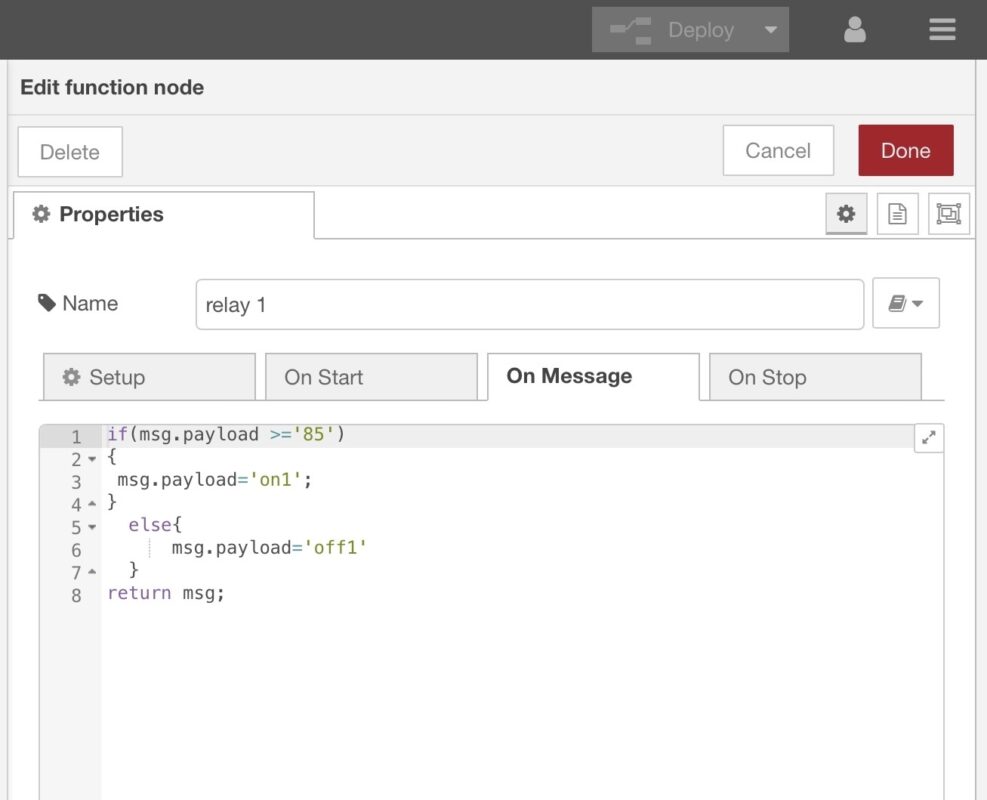
- The node for the second relay says if the battery level is equal to or above 86% send an output of ‘on2’ or else send an output of ‘off2’. This process is repeated for all 8 relays – so the node for relay 8 would say if the battery level is equal to or above 92% send ‘on8’ or else send ‘off8’.
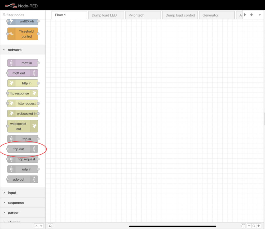
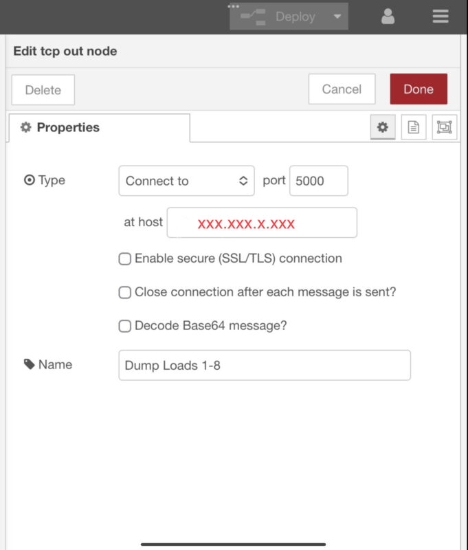
- Next, we need to direct the commands to the relay module, and we do this by using the TCP out node, this node allows us to input the IP address and port of the relay.
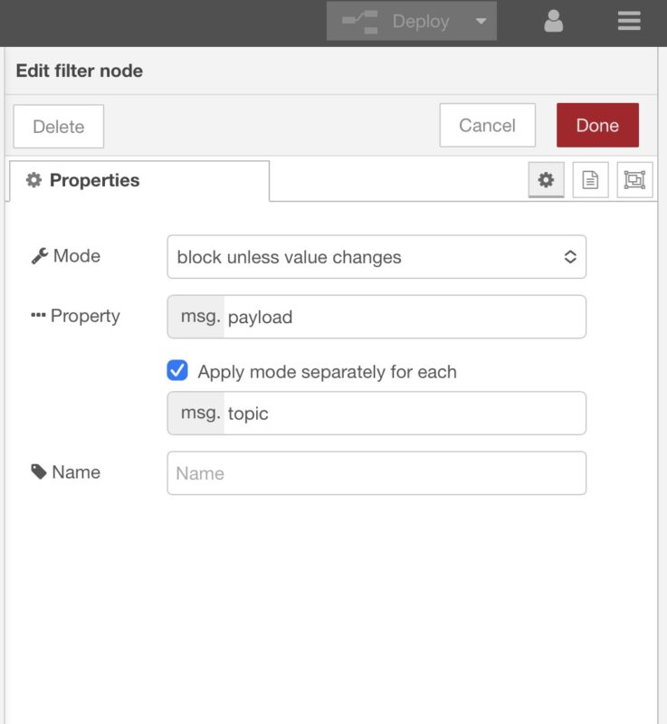
- We also use two other nodes in this flow, we use a filter node – the battery SOC parameter is injected into the flow every 5 seconds from the Victron node, so to stop the network from carrying any unnecessary commands, we use this node to only allow the command through to the relay if it has changed in value from the last command.
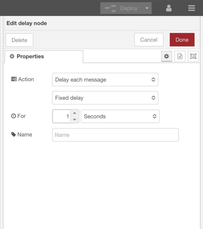
- We use a delay node on each of the relay channels – this is a safety feature! Imagine if there was a communication issue with the system and the batteries were at 100%, once the system was back online, Node RED would turn all the relays on at once which could overload the inverters. By using a delay node, if this situation occurred, the relays would be switched on one by one with a 1 second time delay in between.
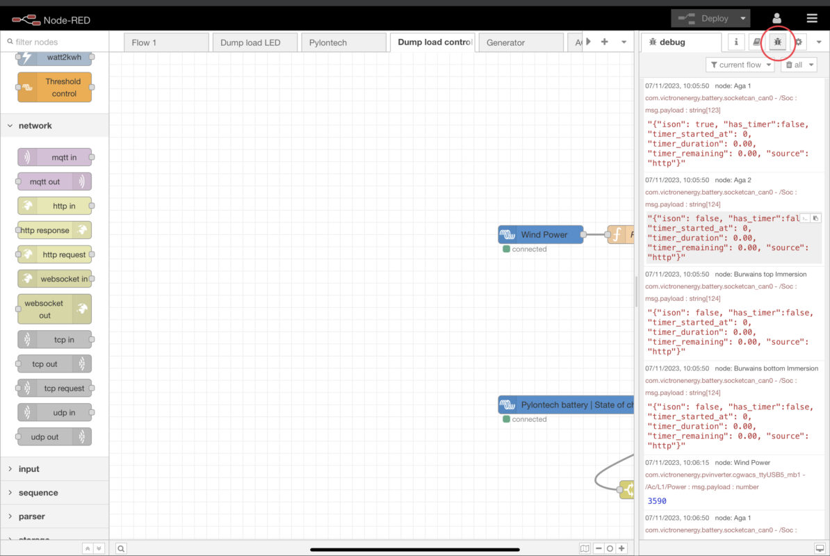
- We use a debug node to confirm the messages are passing through the flow correctly. Once a debug node is used the messages will appear on the right hand side on the screen once the debug tag is pressed.
Basically this flow is querying the battery SOC and then switching on relays dependant on the charge level.
This is only a small example of the possibilities Node RED offers, we are constantly experimenting with Node RED and finding more use cases all the time.
